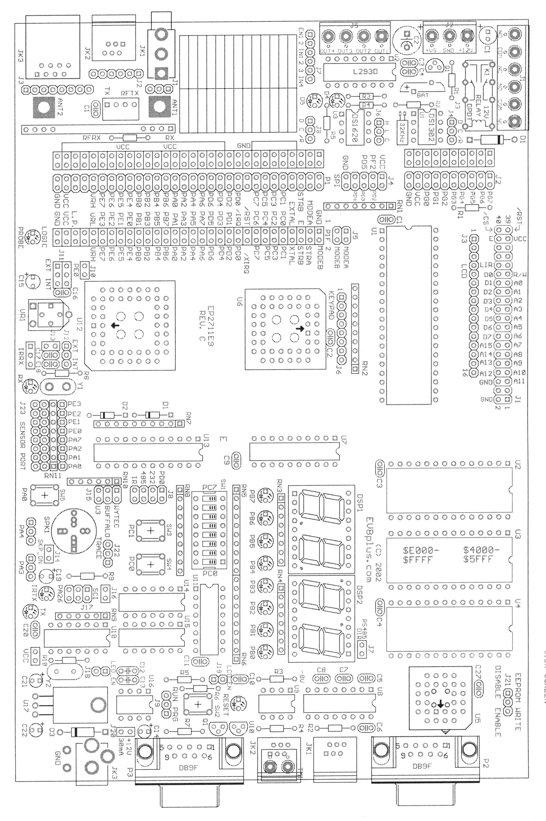
EVBplus2 68HC11 bord voor projecten.
© Harry Broeders.
Deze pagina is bestemd voor studenten van de THRijswijk.
De THRijswijk is in het bezit van een (flink) aantal
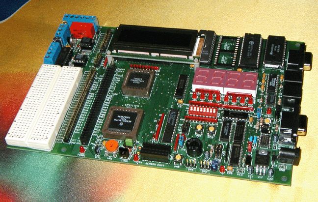
EVBplus2 68HC11
ontwikkelborden. Deze borden worden ingezet bij diverse projecten (onder
andere het Wheatstone Bridge project in P2 en het Hotel project in H1. Als
je z'n bord wilt gebruiken voor een project in H3 of H4 dan kun je z'n bord
bij mij (Harry Broeders, kamer 411) krijgen.
Op deze pagina vind je de belangrijkste verschillen tussen de EVBplus2 en
de EVM die we bij de micocontroller practica gebruiken. De belangrijkste
verschillen:
-
De EVBplus2 heeft een 68HC11E microcontroller in plaats van een
68HC11A microcontroller.
-
De EVB2plus2 heeft een andere geheugenindeling.
-
De EVB2plus2 gebruikt een interrupt jump table.
-
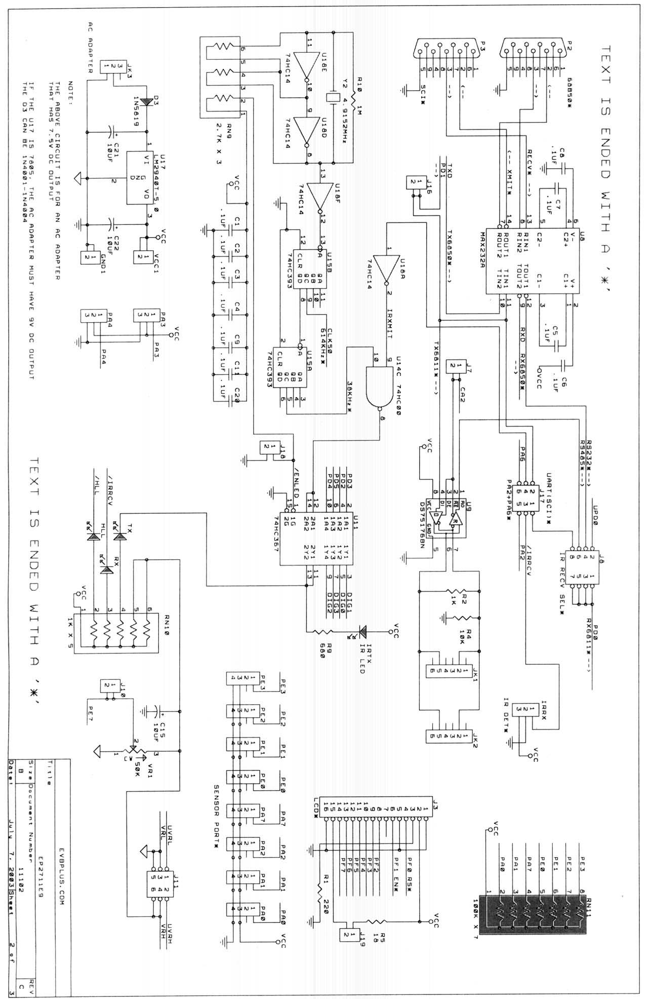
Er is bij de EVBplus2 geen extra kastje nodig voor extra I/O zoals speaker
en potentiometer. Het EVBplus2 bord beschikt over veel I/O
mogelijkheden:
-
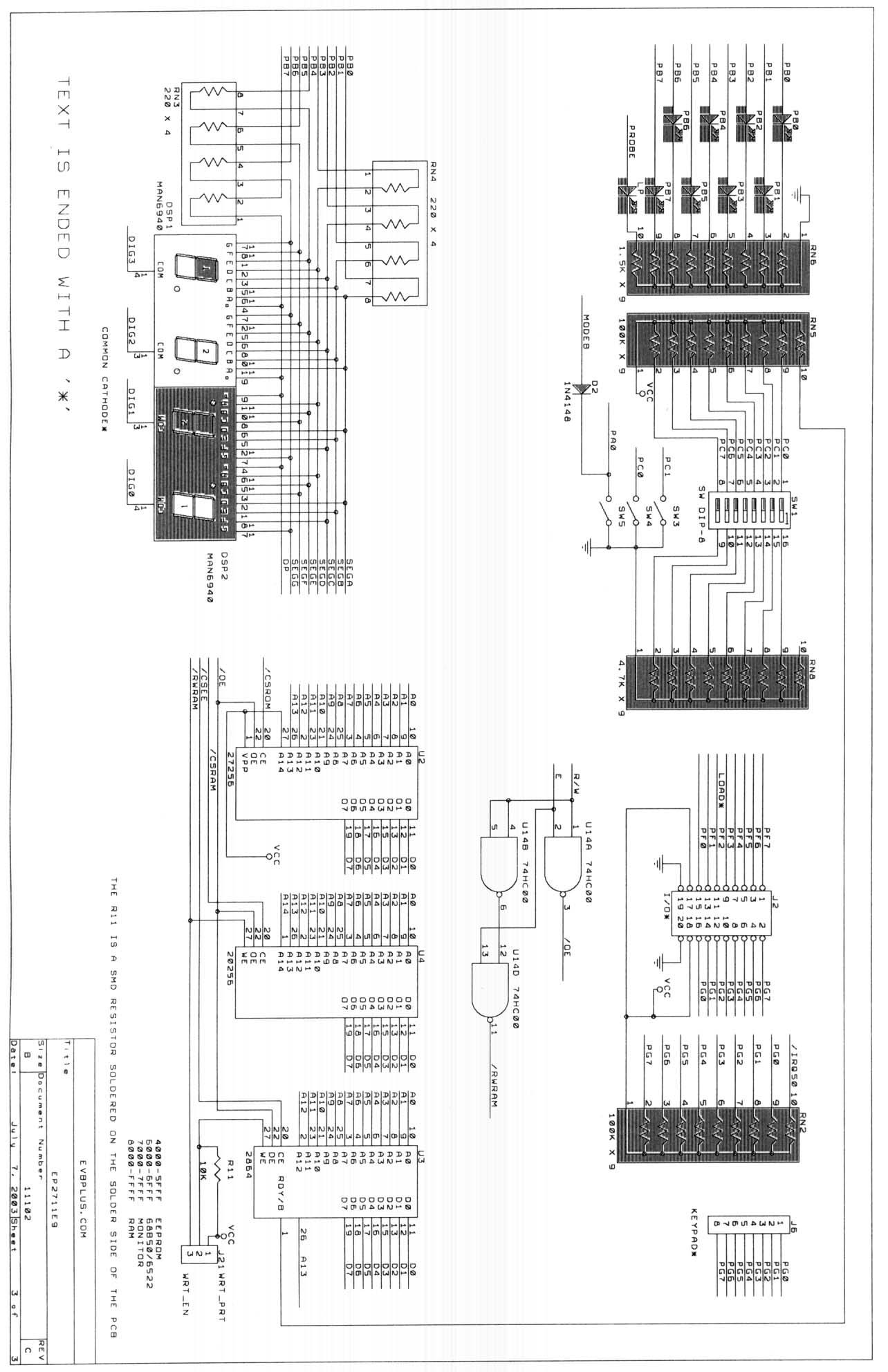
8 leds op de B poort.
-
8 schakelaars op de C poort.
-
16 extra I/O lijnen (deze lijnen worden door de fabricant van het bord poort
F en G genoemd).
-
diverse drukschakelaars (PA0, PC0, PC1 en RESET).
-
4 7-segments displays.
-
infrarood zender en ontvanger.
-
speaker.
-
potentiometer.
-
LCD display.
-
2 seriële RS232 poorten.
-
2 seriële RS485 poorten.
-
SPI poort.
-
experimenteerbordje.
-
...
-
De EVB2plus2 heeft EEPROM geheugen waarin je een programma permanent
kunt opslaan. Je kunt dit programma ook automatisch bij een power-up of reset
laten starten.
-
...
Microcontroller.
De EVBplus2 gebruikt een 68HC11E microcontroller. Er zijn maar weinig verschillen
met de in de EVM kast gebruikte 68HC11A microcontroller. Het belangrijkste
verschil is de pin PA3. Dit is een output pin bij de 68HC11A microcontroller
maar een bi-directionele pin bij de 68HC11E microcontroller.
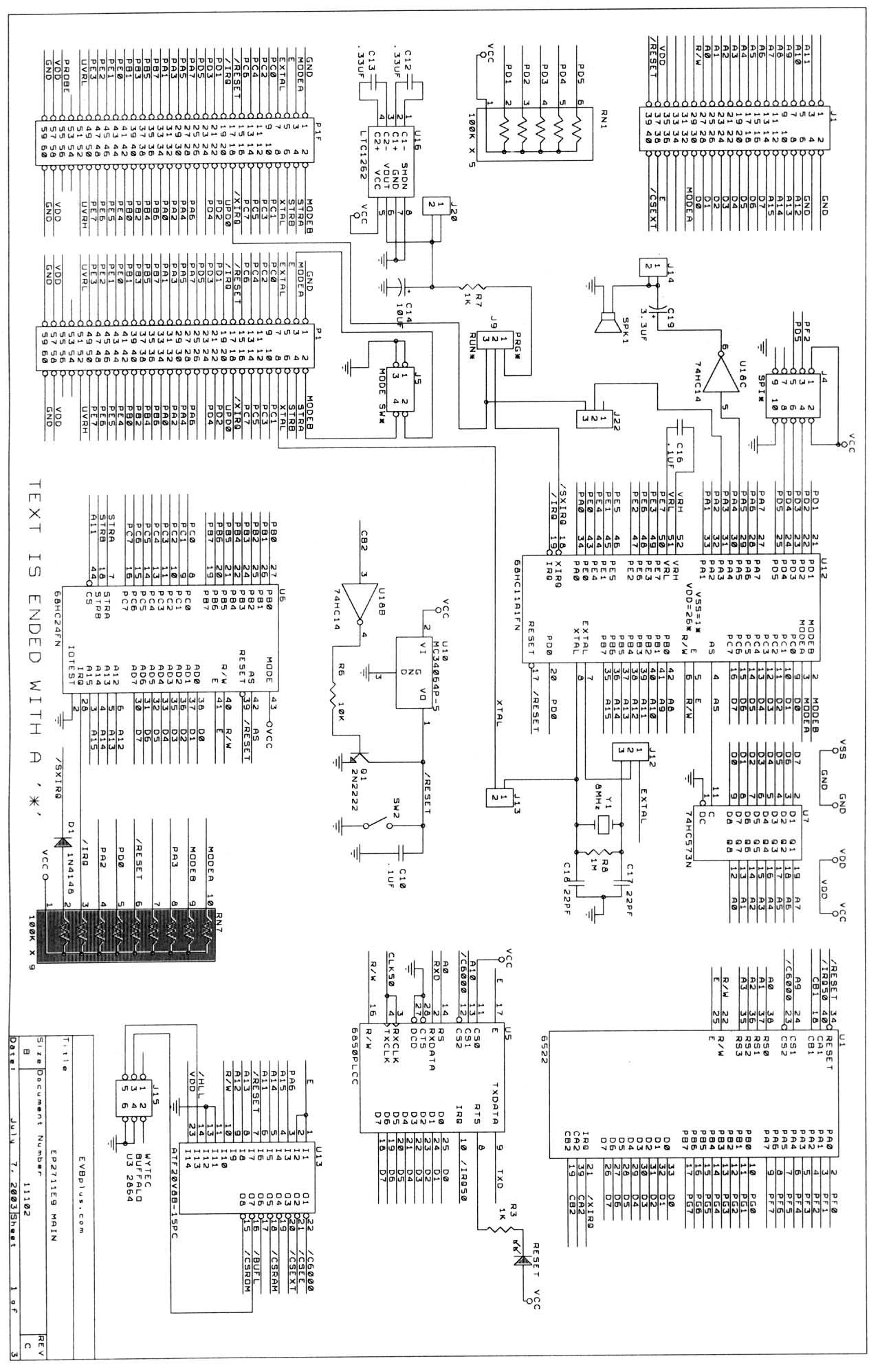
Geheugenindeling.
Het EVBPlus2 bord heeft de volgende geheugenindeling (memory map):
| adressen |
functie |
toelichting |
| $0000-$01FF |
On-chip 512 byte RAM (U12) |
Maar pas op! $002D-$00FF worden gebruikt door het BUFFALO monitor programma.
Dit programma start als het bord wordt gereset met jumper J15 in de middelste
positie (gemarkeerd met BUFFALO) en is nodig om te kunnen debuggen met THRSim11. |
| $1000-$103F |
On-chip I/O registers (U12 en U6) |
De 68HC11E1 (U12) wordt gebruikt in de external mode. Dit wil zeggen
dat de poorten B en C gebruikt worden als adres/data bus om de externe geheugens
aan te spreken. De 68HC24 (U6) port replacement
unit zorgen ervoor dat een "nieuwe" B en C poort ontstaat. De combinatie
van de 68HC11E1 met de 68HC24 gedraagt zich dus als een 68HC11E in single
chip mode met extra (schijnbaar On-chip) geheugen. |
| $2200-$220F |
65C22 VIA (U1) |
Deze chip zorgt voor 16 extra I/O lijnen en bevat ook 2 extra 16 bits
timers/counters. Dit device wordt later uitgebreid besproken. Let op: Doordat
niet alle adreslijnen in de adresdecoder voor dit device zijn gebruikt, vind
je "schaduwen" van deze registers op de adressen: $2210-$23FF. |
| $2400-$2401 |
68B50 UART (U5) |
Deze chip zorgt voor een extra seriële poort. Dit device wordt later
uitgebreid besproken. Let op: Doordat niet alle adreslijnen in de adresdecoder
voor dit device zijn gebruikt, vind je "schaduwen" van deze registers op
de adressen: $2402-$25FF. |
| $4000-$7FFF |
16K EEPROM (U3) |
Dit geheugen kun je gebruiken in je programma om data op te slaan die
behouden moet blijven als de spanning wegvalt. Je kunt ook je programma in
dit geheugen opslaan en "automatisch" laten opstarten als het bord wordt
gereset met jumper J15 in de onderste positie (gemarkeerd met U3). Dit wordt
later nog uitgebreid besproken. |
| $8000-$DFFF |
RAM (U4) |
Deze chip kun je gebruiken voor de opslag van je programma (en eventueel
voor data). |
| $E000-$FFFF |
OTPROM (U2) |
Deze chip bevat de BUFFALO monitor firmware (U2). Dit programma start
als het bord wordt gereset met jumper J15 in de middelste positie (gemarkeerd
met BUFFALO) en is nodig om te kunnen debuggen met THRSim11. |
Voeding.
Om de EVBPlus2 te gebruiken is een 9V adapter nodig.
Debuggen met behulp van de THRSim11 simulator.
Je kunt een programma in het EVBplus2 bord laden met behulp van THRSim11.
Het is ook mogelijk een programma op het bord te debuggen (breakpoints zetten,
registers en geheugen bekijken, single steppen enz.). Let op: jumper
J15 moet op de stand BUFFALO staan, jumper J9 moet op de stand RUN staan
en jumper J22 moet in de stand TRACE staan.
Om programma's voor de EVBplus2 met behulp van THRSim11 te kunnen simuleren
moet het geheugenindeling van de simulator worden aangepast.
-
Start THRSim11.
-
Kies de menu optie File, Options, Memory Configuration...
-
Configureer het geheugen als volgt:
Toelichting:
-
Het On-chip RAM geheugen wordt gesimuleerd door RAM0.
-
RAM1 is uitgezet (disabled) omdat het On-chip EEPROM geheugen van de 68HC11E1
niet bereikbaar is.
-
Het externe RAM geheugen en het OTPROM geheugen (BUFFALO) worden gesimuleerd
door ROM0. Het externe RAM geheugen is bedoeld voor de opslag van een programma.
Omdat we niet willen dat een programma zichzelf overschrijft simuleren we
het als ROM.
-
Het LCD is enabled. Dit maakt het gebruik van de I/O box mogelijk (LED's
op poort B en schakelaars op poort C). De I/O box kan in de simulator worden
geopend via het menu View, I/O box. De in de I/O box aanwezige
LCD display komt echter niet overeen met de LCD display op het EVBplus2
bord. Voor het LCD display is op dit moment nog geen simulatie beschikbaar.
Je kunt nu een eenvoudig assemblertaal programma voor het EVBplus2 bord
schrijven. Bijvoorbeeld (vb1.asm):
portb	equ	$1004
portc	equ	$1003

	org	$8000
start	lds	#$01ff
again	ldaa	$1003	read switches
	staa	$1004	write leds
	bra	again
Dit programma kun je eenvoudig testen op de simulator met behulp van de I/O
box. Als je dit programma op het EVBplus2 bord wilt testen dan moet je de
seriële poort P2 van het bord (rechts boven) verbinden met een COM poort
van de PC. Als het goed is, is een seriële kabel bij het bord aanwezig.
In THRSim11 moet je de communicatie opties via het menu Target, Target
Communications Options... als volgt instellen:
Je kunt nu het programma in het EVBplus2 bord downloaden. Bijvoorbeeld via
de sneltoets Ctrl+D. Via de spatiebalk kun je het programma instructie voor
instructie op het bord uitvoeren. Met de sneltoets Ctrl+F9 kun je het programma
op het target bord starten. De enige manier om het programma daarna te stoppen
is via de reset switch (SW2). Als de PC0 en PC1 dip switches naar boven staan
(en de LED's PB0 en PB1 branden) kun je PC0 of PC1 laag maken door de drukknop
PC0 (SW4) respectievelijk PC1 (SW3) in te drukken.
Je kunt het EVBplus2 bord ook in C/C++ programmeren met behulp van de
GNU gcc compiler. Deze
compiler is opgenomen in de volledige installatie van THRSim11. Meer informatie
over het debuggen van een C programma met behulp van THRSim11 kun je vinden
op:
http://bd.eduweb.hhs.nl/thrsim11/hllsupport.htm.
Het bovenstaande voorbeeld kun je in C als volgt implementeren
(vb1.c):
int main() {
	volatile char* portb=(volatile char*)0x1004;
	volatile char* portc=(volatile char*)0x1003;
	while(1) {
		*portb = *portc; /* copy switches to leds */
	}
	return 0;
}
Om dit programma te kunnen compileren is een link script nodig waarin je
de linker van gcc (onder andere) vertelt hoe de geheugenindeling van de target
is. Je kunt hiervoor de file evbplus2.ld
gebruiken. De geheugenindeling is hierin als volgt gespecificeerd:
MEMORY
{
  ram    (rwx) : ORIGIN = 0x0000, LENGTH = 0x0200
  rom    (rx)  : ORIGIN = 0x8000, LENGTH = 0x6000
}
PROVIDE (_stack = 0x01ff);
Toelichting:
-
Het vrij te gebruiken RAM geheugen loopt van $0000 t/m $01FF. BUFFALO maakt
echter gebruik van de geheugenplaatsen $002D-$00FF. Je moet zelf opletten
dat deze geheugenplaatsen niet door de compiler worden gebruikt. Dit kun
je doen door in het command window van THRSim11 het volgende commando in
te typen:
!readelf -l a.out
-
Het programma moet worden opgeslagen in het geheugen van $8000 t/m $DFFF.
-
De stackpointer wordt in het begin van het programma op $01FF geplaatst.
Je moet zelf opletten dat de stack niet te ver naar beneden "groeit". Het
laagst geldige stackadres is $0100.
Om het programma eenvoudig te kunnen compileren kun je de volgende
makefile gebruiken. Als je wilt weten hoe
dit werkt dan kun je de handleiding voor het programma make vinden op
http://www.gnu.org/software/make/manual/html_node/make_toc.html.
Je kunt het bovenstaande C programma nu als volgt op het EVBplus2 bord testen:
-
Maak een nieuw directory aan en kopieer de files:
vb1.c,
evbplus2.ld en
makefile in dit directory. Let op: Internet
Explorer zet de extensie .txt achter de makefile. Deze extensie moet je
verwijderen.
-
Laad het programma vb1.c in THRSim11. Als het goed is wordt nu de editor
SciTe automatisch geopend.
-
Compileer het programma en laad het resultaat met behulp van de sneltoets
F5.
-
Je kunt het programma nu testen op de simulator met behulp van de I/O box.
-
Je kunt nu het programma in het EVBplus2 bord downloaden door het List Window
te selecteren en de sneltoets Ctrl+D te gebruiken. Je kunt onder andere ook
de CPU registers en de C variabelen op het target board zichtbaar maken.
Documentatie:
-
De volgende documentatie wordt meegeleverd met het bord:
-
De volgende componenten zijn op het bord gebruikt:
-
Wij gebruiken het BUFFALO monitor programma. Dit wordt beschreven in
de
orginele EVB documentatie.
 TODO:
TODO:
-
Interrupts... Zie hoofdstuk 3.3 (page 32) van
de
orginele EVB documentatie. Let goed op want er zitten fouten
in deze tabel!
-
De "Field" die bij "Timer Output Compare 3" hoort is:
$00D9-$00DB.
-
De "Field" die bij "Timer Output Compare 2" hoort is:
$00DC-$00DE.
-
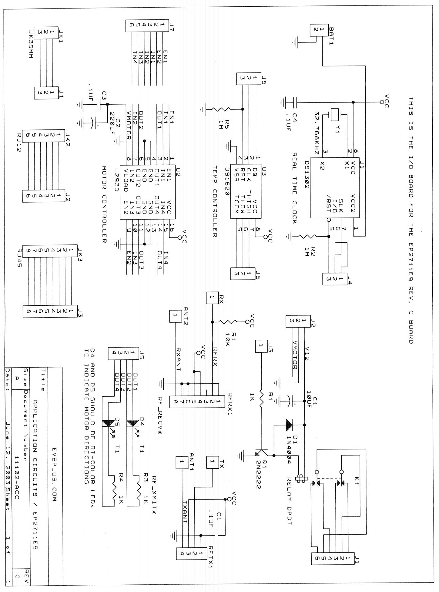
7 segments displays.
-
speaker.
-
potentiometer.
-
Ir zender en ontvanger.
-
Motorsturing.
Voorbeeldprogramma's.
De volgende voorbeeldprogramma's worden meegeleverd met het EVBplus2 bord:
-
Test.asm --- Test program for the Ep2711E9
board (c)2002, EVBplus.com.
This is the factory test program for checking on-board hardware. It
checks the DIP switch of the port C, 8 LEDs of the port B, the pusubuttons
PC0,PC1,PA0, and the LCD display. It displays a shifting number on the 7
segment LED display while playing a song. It allows to adjust the trimmer
pot to change display's brightness.
Instructions:
-
Before running the test program, place the all individual DIP switches at
the upper positions.
-
After running the test program, test each individual switch on the DIP switch
and see the corresponding LED status on the PB0-PB7. LCD display shows: "PRESS
PA0 SWITCH TO CONTINUE TEST".
-
Test the pushbutton switches PC0 and PC1 only when the PC0 and PC1 switches
on the DIP switch are in the upper position. LCD display shows: "PRESS PA0
SWITCH TO CONTINUE TEST".
-
Press the pushbutton switch PA0 and the music should come out. The hex number
0 to F should be shifting out on the 7 segment LED display. The RX LED should
be off and the TX LED should be on. LCD display shows: "TESTING IR LIGHT
NO OBJECT NEARBY".
-
Adjust the trimmer pot, the 7 segment LED display's brightness should change.
If you press any key on the keypad, the 7 segment LED display will show the
key number that you pressed. LCD display shows: "TESTING IR LIGHT NO OBJECT
NEARBY".
-
Place your hand 15 cm from the IR transceiver to allow the IR light reflect.
The both RX LED and TX LED should be on, then observe the message on the
LCD display. See Ir_sen.asm for details. LCD display shows: "TESTING IR LIGHT
OBJECT DETECTED".
-
Ex1.asm ---- Example program 1 for the Ep2711E9
board (c)2002, EVBplus.com.
Reads the DIP switch via the port C and displays its status on the port
B LEDs PB0-PB7.
-
Ex2.asm ---- Example program 2 for the Ep2711E9
board (c)2002, EVBplus.com.
Makes the port B as a binary counter.
-
Ex3.asm ---- Example program 3 for the Ep2711E9
board (c)2002, EVBplus.com.
Displays the word 'HELP' on the 7 segment LED display, the 7-segment
is multiplexed at 5ms per digit fresh rate, 50Hz fresh rate for 4 digits.
-
Ex4.asm ---- Example program 4 for the Ep2711E9
board (c)2002, EVBplus.com.
It displays the word 'SCAn" on the 7 segment LED display, scans the keypad
and displays the key number on the 7 segment LED display if a key is down.
Instruction: Connect a 4 x 4 keypad to the keypad header J6.
-
Ex5.asm ---- Example program 5 for the Ep2711E9
board ((c)2002, EVBplus.com.
User can adjust the trimmer pot VR1 to vary the voltage on the PE7 of
the ADC and to change brightness of the 7 segment LED display.
-
Ex6.asm ---- Example program 6 for the Ep2711E9
board (c)2002, EVBplus.com.
Plays a song via OC3 (PA5).
-
5s_delay.asm ---- 5 second delay timer
for the Ep2711E9 board (c)2002, EVBplus.com
5 second delay routine using the output comparator OC2. The PB0 LED
will be turned on immediately after running the program. It will be turned
off after 5 second delay. Change the DELAY_TIME to 18000 will delay 3 minutes.
-
Lcd1.asm ---- 16X2 LCD sample program for
the Ep2711E9 (c) 2002, EVBplus.com.
This is the simplest way to displays a message on a 16X2 LCD display
module. The cursor is off. If more controls to the display are needed,
see LCD2.asm.
-
Lcd2.asm ---- 16X2 LCD sample program for
the Ep2711E9 (c) 2002, EVBplus.com.
This program displays a message on a 16X2 LCD display module by calling
sel_inst(instruction), sel_data and wrt_pulse subroutines. These subroutines
allow user program to control a different size of LCD display.
-
Ir_sen.asm ---- an IR proximity sensor
for the Ep2711E9 board (c)2002, EVBplus.com.
A robot application by using the IR light beam to detect an object in
its vicinity. Instruction: The PD1 will be reset to low to enable the
IR transmitter. The IR light beam will be bounced back by an object, so the
IR receiver will receive the IR light via PD0 and display the result on the
LCD display module. Sometime the table surface can reflect the light. For
the best result, place the board near the edge of the table to reduce the
reflection by the table surface. Two T1 red LEDs near the IR transceiver
will indicate its status. After running the program, make sure that the TX
LED is on and the RX LED is off without an object in the front of them. If
your body is too close to them, it also will reflect the IR light, so stay
1 foot away from them. When the RX LED is off, then put your hand in the
front of them and read the LCD display. The range is about 12-20 cm and can
be increased by reducing the resister R11's value, but it should not be smaller
than 100 Ohm.